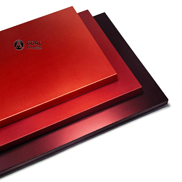
Specifying the wrong surface finish tolerances compromises part functionality, assembly, and lifespan. Engineers constantly face the tension between over-specifying and under-specifying surface treatments during the design phase. Over-specifying increases cycle times, drives up processing risks, and introduces potential fatigue reduction in structural components. Under-specifying leads to premature wear, corrosion failure, or poor dye absorption. This renders the final product visually unacceptable or mechanically deficient. Finding the exact balance requires a systematic approach to determining the correct anodized aluminum coating thickness based on mechanical requirements, environmental exposure, and dimensional constraints. We will break down the electrochemical mechanics, standard specifications, and structural trade-offs necessary to optimize your next component design.
Dimensional Impact: Anodizing is not a purely additive process; coating thickness is split roughly 50/50 between substrate penetration and outward growth, directly impacting machining tolerances.
Categorical Baselines: Type II (Standard) coatings typically range from 0.1 to 1.0 mil (2.5–25 µm), while Type III (Hardcoat) standardizes around 2.0 mils (50 µm) for maximum wear resistance.
Cosmetic Constraints: Optimal dye absorption requires a specific thickness window (typically 8 to 25 µm); exceeding this can result in dark, muddy colors, while falling short yields pale, inconsistent finishes.
Structural Trade-offs: Thicker anodic coatings (especially Type III) significantly increase surface hardness but can reduce the fatigue strength of the underlying anodized aluminum component.
Understanding Anodized Aluminum Coating Thickness Mechanics
How Thickness is Controlled in the Bath
Electrochemical variables dictate the final surface structure of the metal. Current density, electrolyte temperature, and immersion time control the oxide layer growth rate. You must balance these factors to achieve specific engineering requirements. Lower temperatures and higher current densities build thicker, denser coatings. This thermal and electrical combination forms the foundation of Type III hardcoat processing. The chilled bath prevents the acid from dissolving the newly formed oxide layer too quickly. This allows the coating to build substantial depth. Warmer baths produce softer, more porous layers typical of Type II finishes. The higher temperature increases the dissolution rate of the oxide. This creates wider pores that trap colored dyes effectively but resist severe mechanical abrasion poorly. Operators use step-voltage ramping to prevent burning the parts as the insulating oxide layer builds. Starting at a low voltage and gradually increasing it ensures a consistent, dense coating without overwhelming the substrate. Shop floor operators monitor these variables constantly. A slight deviation in bath temperature alters the pore structure entirely. We see this often when chiller systems fail to keep up with the heat generated by high-amperage loads. The resulting finish falls short of the specified depth.
The 50/50 Rule of Dimensional Growth
The 50/50 rule dictates precise dimensional planning. Anodizing does not just sit on top of the metal. It consumes the base metal substrate as it forms the aluminum oxide layer. When you specify a 2.0 mil coating, the oxide layer penetrates approximately 1.0 mil into the substrate and grows 1.0 mil outward. This fundamental mechanic changes pre-machining calculations entirely. If you design a precision shaft, a 2.0 mil coating adds 2.0 mils to the overall diameter. You have 1.0 mil of outward growth on each side of the cylinder. You must machine the raw part undersized to accommodate this outward expansion. Internal bores require the exact opposite approach. Machine internal diameters oversized so the inward growth brings the final dimension down into the required tolerance band. Threaded holes present a unique challenge. The outward growth occurs on both flanks of the thread, effectively quadrupling the dimensional change on the pitch diameter. You must use oversized taps prior to anodizing to ensure standard fasteners fit after processing. Failing to account for this split growth results in parts that fail final assembly inspection. We frequently encounter engineers who forget this rule, resulting in interference fits that require complete part remanufacturing.
![Anodized aluminum components showcasing different coating thicknesses and finishes]()
Standard Specifications and Solution Categories
Type II Anodizing (Standard / Decorative)
Type II anodizing relies on a sulfuric acid bath operating at or near room temperature. It provides reliable general corrosion resistance and excellent cosmetic versatility. The standard thickness ranges from 0.1 to 1.0 mil (2.5 to 25 µm). You will commonly see this finish specified on consumer goods, interior architectural hardware, automotive trim, and sporting equipment. The highly porous nature of this specific thickness range makes it ideal for absorbing vibrant organic and inorganic dyes. The process is relatively fast, energy-efficient, and highly repeatable across large production batches. Operators can process thousands of small parts simultaneously on custom titanium racks. Proper racking is essential. The parts must have a solid electrical connection to the titanium or aluminum splines. Any loose connection causes arcing, which destroys the part and halts the coating process. The moderate bath temperature means the oxide layer remains somewhat soft compared to hardcoat. This softness allows for easier post-process machining if required, though it limits application in high-wear environments.
Type III Anodizing (Hardcoat / Mil-A-8625)
Type III anodizing, often designated as hardcoat or Mil-A-8625 Type III, is engineered specifically for extreme operating environments. It delivers exceptional wear resistance, low sliding friction, and high dielectric strength. Specifications typically demand a thickness of 2.0 mils ± 0.0004 (50 µm). You can customize this based on specific load requirements. Processors achieve this dense layer using chilled acid baths operating near freezing temperatures combined with high voltage parameters. This thick, ceramic-like layer is best suited for aerospace components, firearms, industrial tooling, pneumatic cylinders, and sliding wear surfaces where metal-on-metal contact is frequent. The dense structure resists abrasion exceptionally well. However, the extreme chilling requirements and extended tank times make this process more resource-intensive. Parts require robust racking to handle the high current density without arcing or burning the contact points. Because of the dimensional changes, engineers frequently require masking on critical mating surfaces. Masking involves applying specialized tapes or liquid plugs to prevent the acid from reaching specific areas, keeping them bare and dimensionally unchanged.
Architectural Classes (Class I vs. Class II) & AA Designations
Architectural applications require specific designations to withstand decades of UV radiation and severe weather exposure. The Aluminum Association (AA) categorizes these finishes into distinct classes based on their ability to resist environmental degradation. Class I requires a minimum thickness of 0.7 mil (18 µm) and thicker. You must specify Class I for high-traffic commercial areas, storefronts, or severe exterior environments subject to salt spray or industrial pollution. Class II ranges from 0.4 to 0.7 mil (10–18 µm). It is entirely suitable for interior fixtures or light exterior applications where physical abrasion is minimal. These classes map directly to standard industry finish designations used in architectural blueprints.
| AA Designation | Description | Minimum Thickness | Typical Application |
| A41 | Class I Clear | 0.7 mil (18 µm) | Exterior storefronts, curtain walls, heavy traffic doors |
| A44 | Class I Color (Electrolytic) | 0.7 mil (18 µm) | Monumental buildings, severe weather exposure, coastal facades |
| A31 | Class II Clear | 0.4 mil (10 µm) | Interior partitions, light exterior trim, window frames |
| A34 | Class II Color (Electrolytic) | 0.4 mil (10 µm) | Interior architectural hardware, decorative panels |
Evaluation Dimensions: Matching Thickness to Application Outcomes
Wear Resistance and Surface Hardness
Wear resistance correlates directly with coating density and overall depth. Taber abrasion tests consistently demonstrate that Type III coatings outperform standard bare aluminum by orders of magnitude. They often exhibit wear characteristics similar to hardened steel. We verify wear resistance using Taber abrasers, measuring the weight loss of the coating after thousands of cycles under a weighted abrasive wheel. This empirical data helps engineers validate their thickness specifications. However, more thickness does not always equate to better wear life in every application. Past a certain threshold, the anodic layer becomes excessively brittle. Under high point-loading or severe impact, a coating that is too thick will fracture, craze, and eventually spall off the substrate. You must evaluate the type of wear before defaulting to the thickest possible coating. Sliding friction benefits immensely from a dense 2.0 mil hardcoat. Impact abrasion requires a more nuanced approach. Sometimes a slightly thinner, less brittle layer survives impact better than a maximum-thickness hardcoat.
Corrosion Protection and Environmental Sealing
Corrosion protection depends heavily on both the pore depth generated during the bath and the quality of the final sealing process. Thicker coatings naturally provide a deeper, more robust physical barrier against environmental attack. A properly processed and sealed anodized aluminum component withstands harsh marine environments for years without pitting. ASTM B117 salt spray testing is the industry standard for verifying corrosion resistance. A properly sealed 1.0 mil coating can easily surpass 336 hours of continuous salt fog exposure without showing signs of pitting. Hydrothermal or chemical sealing closes the porous oxide structure. This locks out moisture and corrosive agents. Marine environments demand thicker coatings and extended sealing times using nickel acetate or hot water processes compared to standard atmospheric exposure requirements. If the seal fails, the thickness of the coating matters very little. Corrosive agents will travel down the open pores and attack the base metal. We always verify seal integrity using dye stain tests before shipping parts destined for corrosive environments.
Cosmetic Viability and Dyeing Parameters
Cosmetic viability relies on hitting a specific thickness sweet spot. Optimal dye absorption occurs strictly between 8 and 25 µm. Exceeding this range creates deep, narrow pores that trap excessive amounts of dye. This results in dark, muddy, or off-shade colors. Falling short yields shallow pores that cannot hold enough pigment. This produces pale, washed-out, and inconsistent finishes. We strongly advise against specifying tighter thickness ranges than this standard 8 to 25 µm window for dyed parts. Overly strict tolerances complicate bath processing and increase rejection rates without improving the final cosmetic outcome. Organic dyes fade under prolonged UV exposure. If colorfastness is a priority, specify inorganic metallic salts for dyeing, or rely on the natural electrolytic coloring process used in architectural finishes. Furthermore, Type III hardcoats present unique cosmetic limitations. Due to their extreme density and natural dark gray or bronze tint formed during the chilled bath process, they typically only accept black or very dark bronze dyes effectively. Attempting to dye a hardcoat bright red or blue usually results in a muddy, unappealing brown.
Electrical Insulation (Dielectric Properties)
Anodic coatings act as highly effective electrical insulators. The dielectric breakdown voltage scales linearly with the coating thickness under dry conditions. A standard baseline metric is approximately 800 to 1000 volts per mil of thickness. This makes thick Type III coatings highly effective for isolating electronic components, manufacturing heat sinks, or preventing galvanic corrosion in multi-material assemblies where aluminum contacts dissimilar metals. Quality control teams use dielectric withstand testers to verify the insulation properties. They apply a high voltage across the coating to ensure it does not break down or leak current. Keep in mind that high humidity or surface moisture can bridge the pores and reduce the effective dielectric strength. Proper sealing remains necessary for electrical applications. Engineers often use masking techniques to leave specific grounding points bare while insulating the rest of the chassis with a thick hardcoat.
Implementation Risks and Mitigation Strategies
Managing Edge Defects and Corner Cracking
Sharp edges present a significant manufacturing risk during the anodizing process. Because the oxide layer grows perpendicular to the metal surface, it creates microscopic voids at sharp 90-degree corners. This phenomenon, known as corner spalling, leaves edges highly vulnerable to chipping and premature wear. To mitigate this risk, you must specify minimum radiuses for all internal and external corners based on your target thickness. A general rule is to specify a minimum radius of 0.032 inches for a 1.0 mil coating. Increase that to at least 0.062 inches when specifying a 2.0 mil Type III hardcoat. Thicker coatings require larger radiuses to maintain structural integrity at the transitions. Mechanical deburring or vibratory tumbling prior to anodizing effectively breaks sharp edges and creates the necessary radiuses. This simple pre-treatment step eliminates the risk of corner spalling. Ignoring this requirement guarantees edge failure during assembly or early field use.
Fatigue Strength Reduction
Fatigue strength reduction is a structural reality that engineers often overlook. The anodic layer is essentially a rigid ceramic shell bonded to a ductile metal core. Under cyclic loading or heavy vibration, this brittle outer layer cannot flex with the base metal. It initiates micro-cracks at the surface. These cracks act as stress concentrators and propagate rapidly into the base aluminum. This leads to premature structural failure. The thicker the coating, the more severe the fatigue debit. Aerospace specifications often mandate strict thickness limits on flight-critical components. They require extensive fatigue testing to quantify the exact debit caused by the anodic layer before approving the design. To mitigate this risk on highly stressed structural components, limit the coating thickness to the absolute minimum required for wear resistance. Alternatively, specify shot peening prior to anodizing. Shot peening induces compressive surface stresses that counteract the crack propagation tendencies of the brittle oxide layer.
Alloy Compatibility Issues
Alloy chemistry heavily influences how thickness builds in the acid bath. Different aluminum series react very differently under the same electrochemical parameters. The 2000 series contains high copper levels. The 7000 series contains high zinc levels. Copper dissolves rapidly during the anodizing process, drawing excess current and making it exceptionally difficult to build thick, uniform layers. The 2000 series alloys often struggle to achieve the standard 2.0 mil Type III thickness without micro-arcing, burning, or degrading the part entirely. You must adjust bath parameters, lower the current density, or accept thinner maximum coatings when working with highly alloyed materials like 2024 or 7075 compared to pure architectural alloys like 6061. Cast alloys like A356 contain high levels of silicon. Silicon does not anodize. It remains embedded in the oxide layer, creating a dark, smutty appearance and preventing the formation of a uniform, thick hardcoat. We frequently see engineers specify 2.0 mil hardcoat on 2024 aluminum, which requires immediate design revision to prevent catastrophic part burning in the tank.
Overall Value Influencing Factors and Cost Trade-offs
Process Time and Energy Consumption
Process time and energy consumption drive the final manufacturing efficiency at the finishing facility. Type III hardcoating requires massive industrial chillers to maintain bath temperatures near 32°F (0°C) while dissipating the massive heat generated by high electrical currents. It also requires significantly extended time in the tank to build the full 2.0 mil layer. A standard Type II run might take 30 to 45 minutes in the tank. A full 2.0 mil Type III hardcoat can take up to two hours. This massive difference in tank time dictates production scheduling and overall capacity. Conversely, Type II processing operates near room temperature, requires less electrical current, and finishes much faster. These operational differences directly translate to higher resource allocation for thicker, denser coatings. Furthermore, thick coatings require lower rack densities. Finishers must place fewer parts on each titanium rack to ensure adequate current distribution and cooling flow. This reduces overall batch throughput and extends lead times for high-volume production runs.
Yield Rates and Rework Complexities
Yield rates and rework complexities heavily impact the overall project timeline. If a part fails final inspection due to a cosmetic blemish or dimensional error, stripping and re-anodizing a thick Type III coating removes significant base material. Minor cosmetic defects on thick coatings cannot be easily touched up. Unlike paint, you cannot simply spray over a scratch. The entire part must be stripped and reprocessed, risking dimensional failure. The chemical stripping process dissolves the entire oxide layer, which includes the 50% inward penetration. This almost always pushes precision machined parts entirely out of dimensional tolerance. It turns precision components into scrap metal. Frame your manufacturing strategy carefully. Specify standard commercial tolerances whenever possible. Demanding extremely tight thickness tolerances drastically increases scrap rates. It requires excessive manual bath monitoring and drives up manufacturing complexity without providing proportional functional benefits to the end user.
Conclusion
Define your exact environmental and wear requirements before selecting a finish type to avoid over-specifying thickness.
Select Type II for cosmetic vibrancy and moderate corrosion resistance, or Type III strictly for extreme wear and dielectric insulation.
Adjust your specifications for cosmetic needs by keeping dyed parts within the 8 to 25 µm window to ensure consistent color absorption.
Calculate your pre-anodize machining dimensions using the 50/50 rule to ensure parts meet final assembly tolerances after outward growth.
Consult with a certified metal finisher during the Design for Manufacturing phase to validate alloy compatibility and establish realistic tolerance bands.
FAQ
Q: What is the standard thickness for Type II anodized aluminum?
A: The standard thickness for Type II coatings typically ranges from 0.1 to 1.0 mil (2.5 to 25 µm). This range provides general corrosion resistance, surface protection, and an optimal porous structure for absorbing vibrant organic and inorganic dyes.
Q: How much does hardcoat (Type III) anodizing change part dimensions?
A: Dimensional changes follow the 50/50 rule. A standard 2.0 mil hardcoat penetrates 1.0 mil into the substrate and adds approximately 1.0 mil of outward growth to the surface dimension. Engineers must machine parts undersized to accommodate this specific outward expansion.
Q: Can you dye thick Type III anodized coatings?
A: Yes, but options are highly limited. The dense, thick nature of Type III coatings, combined with the natural dark gray or bronze tint formed during the chilled bath process, restricts color options primarily to black or very dark shades.
Q: What is the difference between Class I and Class II architectural anodizing?
A: Class I coatings are 0.7 mil (18 µm) or thicker, designed for severe weather environments and high-traffic areas. Class II coatings range from 0.4 to 0.7 mil (10–18 µm) and are suited for lighter exposure or interior applications.
Q: How is anodized aluminum coating thickness measured?
A: Thickness is commonly measured using non-destructive eddy current testing equipment in accordance with ASTM B244. For precise or complex geometries, destructive methods like cross-sectional microscopy are used to physically measure the layer depth under magnification.
Q: Does a thicker anodized coating mean better corrosion resistance?
A: While thickness provides a deeper barrier, the quality of the final seal is equally critical for corrosion resistance. Excessively thick coatings can become brittle, craze, and crack under stress, which invites moisture and accelerates localized corrosion.